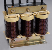
The core reactors have become an inherent element of the modern power electronics and power engineering systems.
The possible locations in the system where the core reactors can operate are presented on the diagram be-low:
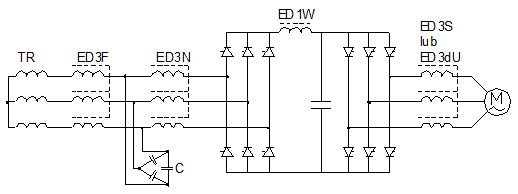
The cores reactors made of electrical sheet are applied within the frequency range up to a few hundred Hz. The basic parameters of reactors include the inductance and rated current. In case of reactors of that type produced by ELHAND these parameters are within the range from a few dozen (µH) to a few hundred (mH), and from a few to a few hundred (A). In alternating current circuits the reactors with steel cores are applied in low-pass output voltage filters or in LC filters allowing for the elimination of selected current harmonics. In direct current circuits the reactors are applied usually for smoothing the characteristics of rectifiers’ output voltages and currents and for ensuring the constant run of rectified current within a wide range of converter operation. It is worthy to mention that the induction reactors are also applied for the compensation of reactive capacitive power.
1. Line reactors of ED1N and ED3N type.
Thyristor converters belong to the receivers which require, in most cases, to apply the line reactors in the cir-cuits which connect the converter with supply network. These reactors fulfill a protective functions in relation to the converter itself and the supply network. The thyristors of converting systems need the protection re-straining the forward current increase until the moment when PNPN structure is switched to the state of con-duction. In such systems it is necessary to use the line reactors.
The application of line reactors in thyristor converters system causes also the weakening of mutual influence between the converters supplied from the same transformer during commutation. Using of reactors causes the decrease of backward current pulse amplitude when the thyristor is switched off as well as the decrease of commutation overvoltages and power emitted in the suppressing circuits. Thus the commutation process runs considerably smoother. Moreover the line reactors protect the supply network against unfavourable in-fluence of converters, limiting the propagation of higher harmonics in the network. In case of line reactors the attention should be paid so that the magnetic core characteristics prevents the reactor from entering into the saturation state within the entire range of expected receiver’s current.
2. Motor reactors of ED1S and ED3S types.
The motor reactors are applied commonly in the converting power transmission systems, both DC and AC. They are installed in the circuits connecting the converter with motor. Depending on the power transmission system type, with which they cooperate, they perform a lot of tasks, including ensuring the motor current continuity and smoothing its pulsation, minimization of the short-circuit current in converter load system as well as the limitation of commutation overvoltages and compensation of the supply line capacitance.
2.1. Tasks of motor reactors in controlled rectifying systems.
The ripples of rectified current in the circuit of motor supplied by a controlled rectifier causes the sparking under the brushes and it makes the commutation process difficult.
Lack of current run continuity in the motor supply system causes unfavourable changes in the run of motor mechanical characteristics and results in the deterioration of the dynamic properties of drive. Therefore one of the most important tasks of ED1S motor reactor is to ensure a maximal possible conduction of continuous current in the converter output circuit. This current takes a non-continuous character the more often the smaller are the values of load current and inductance.
2.2. Role of motor reactors in AC power transmission systems.
Output voltage of converters is a series if rectangular pulses of adjustable width and frequency. The rate of voltage run pulses accretion is very high and endangers to the insulation of supplied machines. Limitation of voltage accretion rate and thus the risk of damage to the motor insulation is achieved by installing the ED3S motor reactor between the motor and inverter.
ED3S motor reactors are applied also in order to limit the shot-circuit currents until the protections are trig-gered and the current is switched off in the circuit. In most cases the selection of appropriate inductance of motor reactor is the only possibility to protect the thyristors (power transistors) of converting systems. The selection of ED3S motor reactor inductance depends on maximal value of short-circuit current in the system. This current cannot exceed the unique peak current value of thyristor (ITSM).
In practice it is often necessary to supply the voltage to drives which are located far away from the supply source. Long supply lines are characterized by great capacitancy, which contributes to a significant increase of power losses in the system. In addition to machine insulation protection the ED3S motor reactor compen-sates the capacitance of the supply line and limits the harmonics and commutation overvoltages in the motor circuit.
3. Passive filter reactors and protective reactors for capacitive batteries of ED3F type.
3.1. Passive filter reactors.
The introduction of thyristor converters for supply and control high-power electric machines caused the
appearance of higher harmonics which get through to the network during the operation of converting driving systems. The systems of higher harmonics filters are used in order to limit an unfavourable impact of the converting systems on the electric network and on the operation of batteries of capacitors which may be connected to that network.
Filters are LC resonance systems in series, switched in parallel into the converter supply circuit. They play a double role: they compensate the reactive power consumed through the power transmission system and prevent the higher harmonic permeation to the power network. Depending on the harmonic number, the filter reactance is as follows:
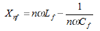 |
| where: Lf ,Cf – inductance and capacity of the circuit branch being a filter; n – harmonic number; ω – pulsation. |
When the induction values and capacities are selected properly for the basic harmonic and for the harmon-ics with numbers lower than nr (resonance frequency), the filter will create a capacitive load and for all the harmonics with higher numbers, it will create the induction load. For the resonance frequency, LC branch will have rather small impendence. The current with the resonance frequency will close between the converter and filter, not permeating to the supply network. In 3-phase systems the filtering circuits for the frequency of 5, 7, 11 and 13 harmonics are applied mostly . For the basic harmonic, the filter branches are always capaci-tive in their character, which means that they reduce the reactive current of the basic frequency.
3.2. Protective reactors for capacitive batteries.
Capacitive compensating batteries installed a dozen or so years ago were not protected with sup-pressing reactors. At present it causes easy to predict operational problems, ending usually with the damage to the battery capacitors. ED3F reactors protect the capacitive batteries against overload-ing with harmonic currents.
In most of industrial networks the installation of many non-linear receivers caused that the level of higher harmonics of voltage and current is dangerous for transformers, motors and, in particular, for the batteries of capacitors. A correct determination of ED3F reactors parameters decided on the efficiency of compensating battery protection. For that purpose it is almost necessary to make the measurements of higher harmonics contents at the designed place of compensating battery operation. An appropriate resonance frequency of the battery–reactor system is selected on the basis of received spectrum of harmonics. In most cases it is a frequency intermediate between those frequencies of voltage and current harmonics, which do not occur in the measuring spectrum or have the smallest share in it. Adjusted battery-reactor resonance system will show an insignificant impedance for harmonic frequencies located in the vicinity of resonance frequency. At the same time it will suppress strongly the currents with frequencies distant from resonance frequency.
4. Compensating reactors of ED3K type.
The group of compensating reactors is intended for compensating capacitive reactive power, resulting from synchronous machines operation and widespread low- and medium voltage cable networks with their insuffi-cient load. Very often the reactors are combined in reactor batteries cooperating with automatic cos regula-tors. Such batteries allow for group, much more efficient follow-up compensation of reactive power, which prevents a possible overcompensation of the network.
The basic operational parameter of such reactors is the reactive induction power produced by them, which is determined from the following formula:
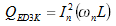 |
| where: In – rated effective value of the sinusoidal alternating current ; ω –rated pulsation; L – reactors inductance. |
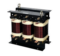
5. Smoothing reactors of ED1W type.
In addition to constant component of voltage and current also the undesirable varying components occur usually in the load system at the output of diode and thyristor rectifiers and converters. A smoothing reactor connected in series with the load allows to obtain a sufficiently small pulsation of voltage and current at high frequency of varying components. Smoothing of voltage and current in the rectifying systems supplied with voltage of industrial frequency with using of a reactor only would require the application of elements with very high inductances. In such a case the reactors is connected with the capacitance, forming LC filter. Important parameters of smoothing reactors, determining its electromagnetic power, are the inductance, rated current value and pulsation amplitude and frequency.
6. Reactors limiting the voltage rise steepness du/dt, ed3du type.
ED3du reactors are installed at the converter’s output. They limit the voltage steepness du/dt circa 2-2,5 times up to 700V/µs and the overvoltage amplitude up to 1000 V. They protect the windings of the asyn-chronous motor stator against overvoltages and allow to lengthen the supply wire up to 100 mb.
The supply network may be endangered to the influence of non-linear receivers causing the deformations of sinusoidal voltage run, and thus the increase of losses and disturbances in the operation of other machines and devices connected to that network.
The line reactors are applied in order to limit the harmonic propagations in local NN networks. Moreover they perform other tasks, such like suppressing the commutation overvoltages and in case of a short-circuit they reduce the value of set short-circuit current and the theepness of its accruing.
Basic functions of line reactors in converters supply systems.
The systems of low-power thyristor converters may be supplied directly from network, without individual transformer. In such circumstances it is necessary to use the line reactors (of ED1N or ED3N type) on the line between the supply network and converter.
These reactors protects both the converter and the supply network.
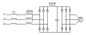
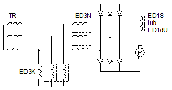
Simplified diagram of converter for supplying the squirrel-cage motor
Controlled rectifiers and frequency converters generate a series of harmonics in the network. These harmonics deform strongly the run of voltage sinusoid, which results in the increase of power losses in all machines and devices supplied from the network.
The line reactors (ED1N or ED3N) limit the propagation of higher harmonics in the network and they suppress the commutation overvoltages arising during thyristors switching over. The application of line reactors causes the weakening of mutual interference of converters during commutation.
The thyristors of converters system often need a protection restraining the accretion of conduction current until the moment when the pnpn structure is switched over to the conduction state. Installation of line reactors is the simplest method to achieve this purpose.
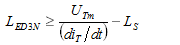
While selecting a reactor an attention should be paid to the mutual dependency between the supply network inductance (LS) and reactor inductance (LED3N), which should meet the condition (1).
 |
(1) |
|
where: UTm – value of blocking voltage possible it a given system at the moment before thyristor switching over; |
|
If it results from formula (1) that LED3N ≤ 0 then it means that there is no need to install the line reactors, because the network inductance limits sufficiently the value of current derivative.
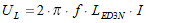
More practical method for determination the technical parameters of line reactors consists in assumption of allowed voltage drop on the reactor which should not exceed several per cents of network rated voltage. Knowing the value of load current we can determine, with using of equation (2), the reactor inductance assuming a several per cent voltage drop on the reactor.
|
|
(2) |
| where: I – rated current of load, f – network voltage frequency, LED3N – line reactor inductance. | |
The characteristics of magnetic way should allow the line reactor to enter into the saturation state within the entire range of expected currents of receiver.

ELHAND line reactor, type ED3N-0,77mH/70A
Thyristor converters are the most commonly used systems for supply and control of electric motors rotational speed. Motor reactors (ED1S or ED3S) are often installed between the motor and the converter system in order to improve the mechanical characteristics and dynamic properties of the thyristor power transmission system.
The motor reactors are applied commonly in the converting power transmission systems, both DC and AC. They are installed in the circuits connecting the converter with motor. Depending on the power transmission system type, with which they cooperate, they perform a lot of tasks, including ensuring the motor current continuity and smoothing its pulsation, minimization of the short-circuit current in converter load system as well as the limitation of commutation overvoltages and compensation of the supply line capacitance.
Tasks of motor reactors in controlled rectifying systems.
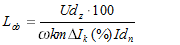
The ripples of rectified current in the circuit of motor supplied by a controlled rectifier causes the sparking under the brushes and it makes the commutation process difficult. Appropriately selected ED1S motor reactor installed in the rectifier load circuit allows to reduce the effective value of the first current harmonic to the allowed level of (2–15) % of the rated current, depending on the motor power and motor angular velocity adjustment range. Knowing the amplitude of a variable component of rectified supply voltage (Udz), the circuit inductance necessary to maintain the allowed value of k current harmonic ΔIk (%) in the circuit is determined from the following equation (1).
 |
(1) |
| where: ω – , m – number of phases, k – harmonic multiply, Idn – rated value of converter current, ΔIk(%) – allowed value of appropriate current harmonic. | |
Knowing the necessary circuit inductance (Lob) and inductance of machine armature (Lt) the inductance of motor reactor (ED1S) limiting the current pulsation in the converter load circuit (2) (rys1) can be determined.
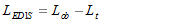 |
(2) |
It is important to remember that magnetic material of the reactor and the motor reactor construction should allow to maintain a constant inductance at the armature current equal to twice value of the rated current. This condition results from converter overcurrent capacity.
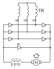
Fig. 1 Simpified diagram of symmetrical 3-phase bridge.
Role of motor reactors in AC power transmission systems.
Output voltage of converters is a series if rectangular pulses of adjustable width and frequency. The rate of voltage run pulses accretion is very high and endangers to the insulation of supplied machines. Limitation of voltage accretion rate and thus the risk of damage to the motor insulation is achieved by installing the ED3S motor reactor between the motor and inverter (Fig .2).
Fig. 2 Simplified diagram of converter supplying the squirrel-cage motor.
ED3S motor reactors are applied also in order to limit the shot-circuit currents until the protections are triggered and and the current is switched off in the circuit. In most cases the selection of appropriate inductance of motor reactor is the only possibility to protect the thyristors (power transistors) of converting systems (Fig. 2). The selection of ED3S motor reactor inductance depends on maximal value of short-circuit current in the system. This current cannot exceed the unique peak current value of thyristor (ITSM).
In practice it is often necessary to supply the voltage to drives which are located far away from the supply source. Long supply lines are characterized by great capacitancies, which contributes to a significant increase of power losses in the system. In addition to machine insulation protection the ED3S motor reactor compensates the capacitance of the supply line and limits the harmonics and commutation overvoltages in the motor circuit. A smoothing reactor (ED1W) is installed in the intermediate circuit of the converter in order to smooth the pulsation and ensure the continuity of rectified current. Optimal selection of its inductance has a significant impact on the operation of the entire power transmission system.
 |
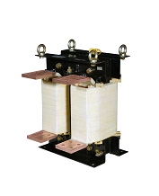
 |
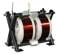
| ELHAND motor reactor , type ED3SM-0,29mH / 250A |
ELHAND motor reactor , type ED3S-0,15mH / 400A |
Reactors limiting the voltage rise steepness du/dt, ed3du type.
ED3du reactors are installed at the converter’s output. They limit the voltage steepness du/dt circa 2-2,5 times up to 700V/µs and the overvoltage amplitude up to 1000 V. They protect the windings of the asyn-chronous motor stator against overvoltages and allow to lengthen the supply wire up to 100 mb.
In the load system of each rectifying system the output voltage is the sum of two components: constant and varying. In order to reduce the pulsation, which are usually unfavourable for the receiver, a rectifying filter is connected between the rectifier output and the load.
ELHAND company produces ED1W smoothing reactors which are applied in the rectifying filters.
Smoothing filters – they serve to correct the shape of time runs of rectifier’s voltage and current. The filter system has a small impact on the value of constant component but it limits the varying component, and thus the pulsation factor.
The properties and efficiency of rectifying filter operation are determined by smoothing factor:
 |
| where: kt1 and kt2 pulsation factors (for voltage and current) at the rectifier output and input, respectively. |
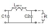
The function of filter is often fulfilled by ED1W smoothing reactor connected in series with the load (Fig. 1a). The inductance of smoothing reactor operating in the output circuit of m-pulse rectifier which supplies the receiver of R resistance, with set bs smoothing factor of output voltage and current is expressed by the following equation:
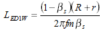 |
| where: R- receiver resistance; r- internal resistance of rectifier circuit; m coefficient depending on rectifier type; bs-smoothing factor; f –frequency of rectifier supply voltage. |
 |
 |
 |
| a) | b) | c) |
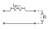
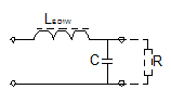
| Fig. 1 The most popular systems of smoothing filters a) inductive , b) inductive-capacitive of G type, c) inductive-capacitive of P type. |
||
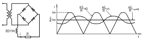
In 1-phase 1-pulse rectifiers with inductive filter it is very difficult to obtain a continuous character of current in the load circuit because the current pulses occur only every second half-period. Therefore the induction filters rather do not cooperate with 1-pulse rectifiers. 1-phase 2-pulse rectifiers with filter in the form of induction reactor are used more often (Fig. 2). In this system the continuous flow of current without big pulsation is achieved already at relatively small load currents.
 |
|
| a) | b) |
| Fig .2 2-pulse bridge rectifier with induction filter. a) diagram of system, b) time runs of currents. | |
If the reactor reactance ωL>>R then the filtration of current pulsation in the circuit is very good. Additional advantage of this system consists in that the average current value does not depend on inductance.
The limitation of current pulsation through the increase of reactor inductance does not cause the voltage losses.
Rectifying filter in the form of ED1W smoothing reactor is much more effective if it cooperates with rectifier, in which the varying components has several times higher frequency (e.g. in pulse converters).
In practice the induction filters are applied mostly in 3-phase system of higher power values.
The structure of LC filter (Fig. 1b, 1c) with parameters favourable both at low and high load currents is obtained by connecting a smoothing reactor with capacitor. In this system the reactor constitute a serial impedance and the capacitor additionally shunts the load for varying components. The reactors of ED2W type are often used version of smoothing reactors.
They have two independent windings located on the core, in shape of UI .
They are used in the systems cooperating with high-power multi-pulse converters.
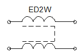
Fig .3 Diagram of ED2W smoothing reactor.
If the efficiency of a single filter is too small, then it is possible to obtain a further reduction of varying component by the construction of multistage filter consisted of several links connected in cascade. A resultant smoothing factor is as follows:
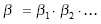 |
| where: b – smoothing factor of multistage filter; b1 ,b2 – smoothing factor for successive filter stages. |
The application of smoothing filter has a significant impact on the output characteristics of the entire rectifying system. Considerable oscillation of current of voltage caused by resonant character of LC and its significant quality factor may occur in the circuit in non-fixed states arising during switching the rectifier on and off.
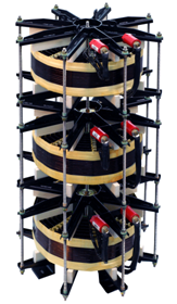
ELHAND smoothing reactor, type ED1WHX-40mH / 600A; 6kV
ELHAND smoothing reactor, type ED2W-2x0,033mH / 3500A
Protective reactors of ED3F type protect the capacitive batteries against overloading with harmonic currents.
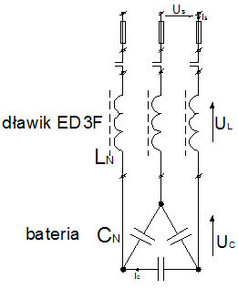
Fig.1 Diagram of one stage of compensating battery with suppression reactors.
Description: Dławik – Reactor, Bateria - Battery
As a result of installation of many non-linear receivers the level of higher harmonics of voltage and current is dangerous for transformers, motors and, in particular, batteries of capacitors. Correct determination of the parameters of ED3F protective reactors decides on the compensating battery efficiency. For that purpose it is almost necessary to measure the contents of higher harmonics at the planned place of compensating battery operation. On the basis of measured spectrum the appropriate resonance frequency for battery-reactor system is selected. Usually it is the frequency intermediate between the frequencies of these voltage and current harmonics which are not present in the measuring spectrum or have the smallest share in it. The battery-reactor resonant system will show an insignificant impedance for harmonic frequencies located in the vicinity of resonance frequency. Simultaneously it will strongly suppress the currents with frequencies distant from fR resonance frequency.
Selection of optimal resonance frequency of the system (e.g. fR=189Hz) and knowledge of network frequency (fN=50Hz) at which the battery will operate allow to determine the p% suppression factor(1), which will be then used in simplified calculations.
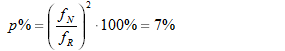 |
(1) |
Table 1. Examples of resonance frequencies in battery-reactor system:
| Suppression factor - p% | 5% | 5,67% | 7% | 12,5% | 14% |
| Resonance frequency - fR | ~224 Hz | ~210 Hz | ~189 Hz | ~141 Hz | ~134 Hz |
Each stage of a compensating battery is protected with a protective reactor of inductance determined for the battery stage capacitance and assumed resonance frequency of the system. It is necessary to determine the power (QCN) and rated voltage (UCN) of capacitors which form the individual stages of the compensating battery. It allows to conduct correct calculations in order to determine the IS currents in the circuits and the inductance (LN) of protective reactors.
On the basis of equation describing the capacitor power (e.g. 25kVar/440V 50Hz), the capacity of compensating battery stage can be determined as follows (2):
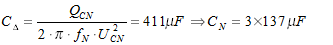 |
(2) |
Then the capacitive reactancy (XC), inductive reactancy (XL) and the resultant reactancy of battery with reactors (XBAT) (3,4,5) are determined, with assumption that the resonance frequency of the system should ~189Hz (p=7%).
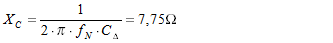 |
(3) |
 |
(4) |
 |
(5) |
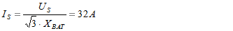
On this basis the LN phase inductance of reactor and IS current forced by the battery can be determined (6,7):
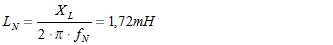 |
(6) |
 |
(7) |
The actual voltage (UCR) on the battery terminals will achieve the following value (8):
 |
(8) |
Hence the actual reactive power (QCR) of 25kvar/440V 50Hz capacitive battery, reactive power of protective reactor (QL) and the resultant reactive power of battery stage (QBAT) can be determined (9, 10, 11):
 |
(9) |
 |
(10) |
 |
(11) |
ED3F protective reactors are required to operate properly in the conditions of changeable load. The share of harmonic currents loading the battery and reactors is varying depending on the configuration of factory network and the number of converters or other non-linear receivers operating at a given time. Therefore the parameter called the magnetic linearity was determined. This parameter represent the maximal reactor current (ILIN), for which the inductance tolerance should be within the range L ≥ 0.95LN. It is the measure of reactor parameters stability during overloading.
The intensity of network voltage sinusoid deformation at the place of capacitive battery operation may depend, to a significant extent, on non-linear receivers operating in neighbouring companies supplied from the same switching stations. Attention should be paid that the number of deformations (i.e. THDU, THDI) may change radically within only several months (as the successive devices, e.g. converters, are installed in the neighbouring companies). Therefore the installed compensating systems should be equipped with protective reactors, in order to avoid the operational problems.
ELHAND reactor intended for protection of ED3F-22,2/400/7-25/440 battery
Reactors for passive higher harmonics filters.
The significant level of the higher harmonics in industrial and municipal power networks is caused by the fast growth in the number of exploited converters and non-linear receivers exploitation. The voltage sinusoid deformation leads to increase in losses and, in extreme situations, even to the disturbance in the machines and devices operation. In order to limit the unfavourable impact of the non-linear receivers and converters on electric and power networks, the higher harmonics filters systems are used on the machines supplied from them and on batteries of the capacitors connected with the network.
Our company produces protective reactors of EDLC type intended for operation in the systems of LC higher harmonics filters.
The tasks of the higher harmonics filters in power networks.
In the most common 3-phase bridge converter systems (6-pulse systems), the current run on the transformer primary side – assuming the symmetry of supply voltages, commutation impedance and delay angles of thyristors switching off – will include, in addition to the basic component, at least the following harmonics: 5, 7, 11, 13, whose numbers are defined by the general equation (1).
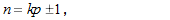 |
(1) |
| where: n – harmonic number, k – natural number, p – rectified voltage pulse number. | |
The values of the harmonics components amplitudes may be determined by using the equation (2).
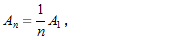 |
(2) |
| where: A1 – amplitude of voltage basic harmonic, An – amplitude of nth harmonic. | |
Too high contents of the supply current higher harmonics may cause a considerable increase of power losses in devices and machines cooperating with the converter as a result of the current flow with increased frequency, or it may cause disturbances in the operation of the device by deforming the supply voltage. This particularly refers to capacitors batteries, operating in parallel with the converting system. Decreasing the capacitor’s impedances, combined with frequency growth, may cause damages to the battery resulting from overloading with the currents of the higher harmonics frequencies.
Moreover, the parallel resonance in the system is also a dangerous phenomenon. The harmonics produced by non-degree power transmission systems may be enforced as many as 10-15 times in the parallel resonance circuits, formed by capacitive reactance of the capacitors batteries and network induction. This phenomenon may result in damaging both the capacitors batteries and converters.
In unfavourable conditions, the component harmonics may pose a threat to the mechanical structures of electrical machines. The harmonic pairs, e.g. 5 and 7, may produce mechanical vibrations in the generator or motor at the frequency of 6th harmonic
These vibrations arise as a result of the turning moment fluctuations due to deforming the supply voltage curve. When the frequency of these vibrations converges with the mechanical resonance frequency, the machine’s mechanical structure will be susceptible to considerable overloads.
The strenuous effect of the noisy operation of the electrical machines, resulting from the phenomenon of magnetostriction, is additionally reinforced due to the relatively high frequencies of the current harmonic components. The currents, deformed by the higher harmonics content, also cause a significant and more intense heating of the power ducts and cables as a result of the skin effect phenomenon or vicinity effect.
The task of LC filters that comprise the ED3LC reactors is to limit the negative impact of the current higher harmonics on the power network and all the devices connected to it.
Figure 1 shows a typical system for compensating reactive power and harmonics filtration. There are three filtering branches here, adjusted to 5, 7 and 11th harmonic. The number of installed filtering branches depends on the reactive power necessary for the compensation and on measurements as well as the precise analysis of the respective harmonics content in the network.
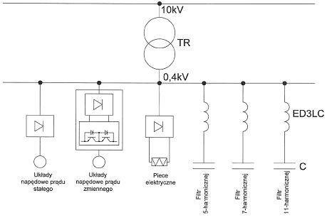
Fig. 1 Simplified diagram for the reactive power compensation circuit and harmonics filtration.
Filters are LC resonance systems in series, switched in parallel into the converter supply circuit. Their function is twofold: they compensate the reactive power consumed through the power transmission system and prevent the higher harmonic penetration to the power network. Depending on the harmonic number, the filter reactance is as follows (3).
.png) |
(3) |
| where: Lf ,Cf – inductance and capacity of circuit branch being a filter; n – harmonic number; ω – pulsation | |
When the induction values and capacities are properly selected for the basic harmonic and for the harmonics with numbers lower than nr (resonance frequency), the filter will create capacitive load and for all the harmonics with higher numbers it will create the induction load. For the resonance frequency, LC branch will have rather small impendence, in practice equal to the reactor winding resistance. The current with the resonance frequency will close between the converter and filter, not permeating to the supply network. For the basic harmonic, the filter branches are always capacitive in their character, which – in practice – means the execution of the reactive power compensation (figure 2.)
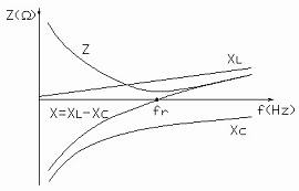
Fig. 2. LC filter impedance characteristics.
There are many solutions in industrial applications. However, the LC passive LC filters are most common (Fig. 3).
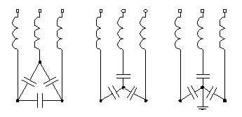
Fig. 3. Example of LC filters systems.
While operating, the branches of LC filter, shown in Figure 3a, are under the network forward voltage. In connection therewith, the capacitors batteries and reactors will be considerably more expensive than in the systems, especially in the scope of medium voltages (Figure 3b,c). For this reason, the filter configuration (Figure 3a), is commonly used in the low-voltage systems. The drawback of this solution is the lack of the possibility to filter the triple harmonics. This is possible only in the star system with an earthed zero point.
In the system shown on Fig. 3b, the distribution of voltages at the respective filter phases depends on the capacity and induction of each branch. Due to the necessity to ensure a proper working voltage in all the three phases, a precise symmetry of capacity and induction is required. The systems (Fig. 3a,b) may be used in any three-phase network system. However, the system shown on Fig. 3c may not be applied in the network with an insulated zero point or a zero point earthed by an arc-suppression coil. In such a system, the filter branches operate practically under equal voltages (Up/√3). case of short-circuit with the earth in one phase, the inter-conductor voltage Up appears on the other branches. This voltage is √3 times higher than in the state of normal operation. The capacitors battery in this situation should be switched off as soon as possible (t ≤ 1min.). However, in the networks with an insulated zero point, usually only earth faults are signalled and last longer, which poses a serious threat to the filters systems.
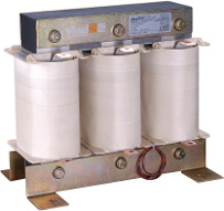
ELHAND filtration reactor, type ED3LC-0,5mH/250A.
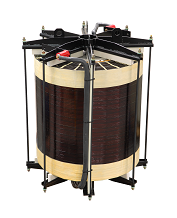
Our company produces the coreless (air) reactors, 1-phase and 3-phase.
We perform the projects according to the individual technical requirements of our Customers.
Our air reactors have a linear voltage-current characteristic, i.e. the effect of ferromagnetic saturation does not occur. The air reactors are characterized by the smaller weight in comparison to the core reactors.
The losses occurring in the coreless structure of the air reactors are increased due to the strong dispersion of the magnetic flux.
The air reactors fulfill the function of inductive elements smoothing or limiting the rate of voltage slope accrual (du/dt). They cooperate with low-voltage and medium-voltage converters.
ELHAND air reactor, type 3xED1PH-2mH/540A; 6kV
ELHAND air reactor, type 2xED1P-4mH/170A; 0,75kV; 300Hz
