A transformer transfers alternating electrical electrical energy, where frequency remains unchanged and the voltage and current parameters can be changed. Transformers are generally applied when it is necessary to provide the consumer with different voltage and current parameters than are provided by the electrical power source.
A transformer has at least 2 windings having galvanic separation. The windings are integrated onto a magnetic core with a physical form of columns linked by yokes through which the magnetic flux permeates. The windings reside on the core columns. The core material consists of metal sheets which are insulated from each other.
![]()
1-phase transformer
The windings are identified as primary or secondary, depending on the direction of energy flow through the transformer. The primary winding absorbs energy from the power source, while the secondary winding delivers energy to the load. The ratio of primary to secondary winding turns (Z1/ Z2) is approximately equal to the ratio of primary to secondary voltage.
Voltage U1/ U2 and it is called the transformation ratio ϑ.
![]()
Transformer windings can have a cylindrical or disk form, depending on its intended use and properties.
Windings are usually made of copper, although aluminum is sometimes used.
The windings are separated from each other by means of:
- basic insulation – for isolation transformers
- additional or reinforced insulation – for separation transformers
Depending on the degree of protection against electric shock the transformers can be made in three classes of protection ( I; II; III ).
Depending on the cooling medium the transformers are divided into dry-type and oil transformers (cooled respectively with air or oil) and where circulation is natural or forced.
A transformer supplying a motor should be selected in such a way so that it will not change the motor parameters. During start-up the motor absorbs a high current which causing a big voltage drop at the secondary of the transformer and a significant voltage drop supply network. This has an adverse influence on the operation of other loads and can result in the stalling and contactor drop leading to blackout of loads. Reduction of voltage during start-up can be limited to an admissible range (usually Uallowed ≥ 0.85xUn), by application of a bigger transformer and larger cabling, but it increases the cost of installation. It is therefore better to reduce motor starting current to avoid an unnecessary oversizing of network elements, including transformer.
A simplified selection of transformer power rating to suit a 3-phase motor is presented below. The power specified on the rating plate of the motor is the rated mechanical power (Pn) delivered to the shaft. This is real power expressed in kilowatts (kW). The real electrical power (P) absorbed the the motor at rated load depends on the motor efficiency and can be expressed by the following formula:
 |
| where: Pn – mechanical power returned on motor shaft, ηn – motor rated efficiency |
The current absorbed by motor during normal operation and rated mechanical load depends on power factor of motor and it is expressed by the following formula:
 |
| where: Un – motor rated voltage, cos φn – power factor at rated load |
The total power (Sc) absorbed by motor during rated operation is the apparent power expressed in kVA, which is expressed by the following formula.

The transformer supplying a 3-phase motor should be selected with a higher apparent power (ST) than the power (Sc) absorbed by the motor. St is expressed in kVA accordance to the following simplified formula:
| where k is a coefficient ( k > 1) |
The k coefficient may be omitted when selecting transformers for low-power motors.
For higher power motors, the coefficient k should be taken into consideration.
The value of k coefficient depends on torque, starting current, start-up duration and power factor at motor start-up.
Note: Power factor at start-up it is considerably lower than at rated load.
An autotransformer is a special variation of a transformer in which the primary and secondary windings are combined into one winding, affording no galvanic separation of circuits.
The ratio of turns counted on the primary side to that on the secondary side determines the primary to secondary voltage ratio. This is the same as a conventional transformer, except the winding forms both part of primary and secondary. The formula for turns and voltage ratio is given below, together with diagrams of both conventional and auto transformers.
![]()
Diagrams of transformer and autotransformer
The amount of iron and copper used for autotransformer construction is considerably smaller than a conventional transformer due to the galvanic combination of both windings. The auto transformer offers reduced losses (increase in efficiency) as well as reduction in weight, size and price.
Comparing a transformer and an autotransformer with the same transitive (output) power SPRZECH , the autotransformer has lower electromagnetic power (core power factor) SWT :
![]()
and therefore it is lighter:
| where: SPRZECH – autotransformer transitive (output) power, SWT – transformer electromagnetic power, mA, mT – autotransformer and transformer respective weights. |
Example :
- if power output SPRZECH = 100 kVA;
- primary and secondary voltages U1 = 230 V, U2 = 115 V
- then – autotransformer electromagnetic power

- and respectively the relation of autotransformater and transformer weights is as follows

It results from above that for transformation of 100 kVA it is enough to apply a step-down autotransformer with a core corresponding to the power of 50 kVA transformer, and the weight of autotransformer will be about 60% of that of the 100 kVA transformer.
Reduction of autotransformer weight and dimensions is its advantage in relation to a transformer, however an autotransformer has the following disadvantages:
- galvanic combination primary and secondary circuits meaning disturbances and over-voltage are transmitted directly to the secondary circuit.
- earth faults in the power network are transmitted by the autotransformer which can result in risk to the user.
- short-circuit voltage is lower as given by the following formula.:
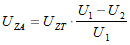
where: UZA, UZT – short-circuit voltage of autotransformer and transformer, respectively
Therefore the application of an autotransformer is limited. They are applied for example in electromagnetic systems for connecting networks with different voltage levels, in start-up systems of large squirrel-cage induction motors, in laboratories, and everywhere where the lack of galvanic separation of primary and secondary circuits is allowed and where the advantages resulting from lower weight and losses exceed the expenditures associated with reduction of short-circuit current. Autotransformers are not allowed in mining, medical or nautical applications.
![]()
Autotransformer ELHAND, type EA3M-8/30kVA
Depending on power and type of induction motors their start-up can be conducted by:
- direct connection to the supply network,
- decrease of motor supply voltage (star/delta switch or autotransformer),
- increase of rotor circuit resistance (starter),
- change of the number of pole pairs (pole switch),
- change of supply voltage frequency (frequency converter)
An autotransformer can be used for current reduction at start-up of high power asynchronous squirrel-cage motors.
The autotransformer provides a lower voltage at start-up in a similar way that star-delta switching reduces current. The internal impedance of the autotransformer helps limit start-up current within the network, in a way which is not available with star-delta switching.
The advantage of this way of start-up is lowering of the following currents:
- current flowing in the motor winding (IRS) – it is lower by autotransformer ratio:

- current absorbed from supply network during the start-up (I1) – it is lower by autotransformer ratio square:

The disadvantage of this way of start-up is that the motor initial torque (MPR) is decreasing to the same degree as the current absorbed from network:

where: ϑ–autotransformer ratio , IP – initial start-up current when supplying the motor with full voltage, IRS – current flowing in winding motor, I2 – autotransformer secondary current, I1 –autotransformer primary current (absorbed from supply network), MPR –motor initial moment when supplying from autotransformer, MP – initial moment developed by the motor at full voltage
Therefore when selecting the ratio of start-up autotransformer it is always necessary to ensure that the torque developed by the motor at lowered voltage is greater than the torque of driven machine resistance.

Start-up system of the squirrel-cage induction motor with start-up autotransformer
The system presented on the drawing above is a commonly used solution for start-up of asynchronous motors. The start-up is conducted in two stages, without occurrence of voltage-free interruptions and it lasts for a period of 20 to 30 seconds.
Initially the motor runs at a lowered voltage provided by the autotransformer (Q1 and Q2 contacts are closed and Q3 contact is open). At this time start-up current is limited by a suitable selection of autotransformer ratio. Next Q2 is opened, where the motor is supplied from the network via the series impedance of the autotransformer windings, which are connected in series. Thus the windings function as chokes limiting the start-up current. Finally, when the motor achieves an appropriate rotational speed, Q3 is closed, where the motor is supplied with full voltage directly from the network.
If necessary and after agreeing with Customer ELHAND can produce the start-up autotransformers with several taps. Remember that the value of start-up current is significantly greater than autotransformer rated current. Thus, in order to avoid the overheating of the autotransformer windings after multiple start-ups, the winding temperature is monitored using of temperature sensors installed inside the winding.
![]()
Start-up autotransformer ELHAND, type EA3R, with temperature sensors.
Medical isolating transformers are the main element of sets for supplying IT insulated electric network in medical rooms. The technical requirements for these transformers specified in EN 61558-2-15 standard are very strict, in order to ensure a reliable and safe operation.
These transformers can be made in 1-phase (ET1MED type) and 3-phase (ET3MED type) versions. In accordance with above-mentioned standard the range of allowed power is from from 0.5 to 10kVA. Moreover the primary (supply) voltage is limited to 1000V, and the maximal secondary voltage is limited to 250V. Rated frequency of medical separation transformers should not exceed 500Hz.
In order to meet earth leakage current requirements, reinforced insulation is applied in the construction of these transformers. In accordance with EN 61558-2-15, the leakage current between the transformer secondary winding and earth, measured in no-load state, should not exceed 0.5mA. The leakage current between the screen and earth, measured in no-load state, should not exceed 3.5mA.
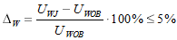
Other requirements relate to no-load secondary voltage, no-load current and short-circuit voltage. ΔW difference between UWJ no-load secondary voltage and UWOB secondary voltage under load, expressed as the percentage of secondary voltage under load, should not exceed 5%:
No-load current of medical separation transformers should be limited to maximum 3% of rated primary current when suppled with rated voltage, and the short-circuit voltage should not exceed 3% of rated supply voltage.
![]()
Connection diagrams of medical separation transformers of ET3MED and ET1MED types.
In emergency states the medical transformers must operate with overload. An overload level of 1.6xIn for 1 hour or 2xIn for 30minutes is allowed. The transformer operating temperature is supervised by a relay cooperating with temperature sensors. Medical transformers of ET1MED and ET3MED types are equipped with PTC and PT1000 temperature sensors, which are installed in windings and allow for efficient control of transformer operation.
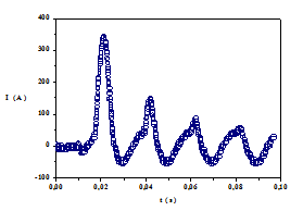
An important parameter specified in EN 61558-2-15 standard is a inrush current. The referred standard requires that transformer construction itself (without application of additional elements in installation) should limit the value of inrush current to 12-times peak value of the rated primary current.
 |
|
| Example of inrush current for ELHAND transformer of type ET1MED-6,3kVA, under load . | |
Converting systems are usually supplied by means of a transformer, the parameters of which are adjusted to the converter requirements. Converting transformers operate in extremely hard conditions. Their secondary currents comprise the whole range of harmonics. The qualitative and quantitative content of the current harmonics depends on the converter system in which the transformer operate.
Converters systems with neutral conductor. Here the current on the transformer secondary side takes the shape of unidirectional rectangular impulses. This causes a DC component of core magnetization which is a negative effect from the viewpoint of the transformer. Hence these converting transformers are usually larger and heavier than typical supply transformers because, by design, they must have lower induction to take account of the high harmonic content in the secondary.
In addition to adjusting the voltage level to the load requirement, the converting transformer provides protection to the converter thyristors. The converting transformers have considerable leakage inductance which limits current during thyristor commutation. The are also equipped with reinforced winding insulation. These properties cause that the dimensions and price of converting transformers to be greater comparing to traditional ones.
Converting transformers are configured in a variety of ways to suit the converting system. One of the simplest configurations is a transformer for 3-pulse converters systems. Here the primary windings are connected in delta, while the secondary windings are star connected with a neutral terminal (Dyn group):
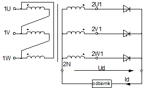
Diagram of 3-pulse converter with neutral conductor.
The transformers intended for 6-pulse converters systems are applied much more widely. Such a system is supplied via a transformer or line chokes. The transformer is used when it is necessary to adjust the converter output voltage to the required receiver voltage. The converter bridge system does not require directing the neutral conductor on the transformer secondary side and its
windings may form the following combination systems: Yy, Yd, Dy, Dd.
Another constructional solution is a special transformer for supplying the six-phase. The primary windings of the transformer are connected in delta and the secondary ones are combined into 6-phase system with an external neutral terminal:
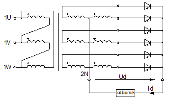
Diagram of 6-pulse converter with directed neutral conductor.
Multi-pulse complex converting systems are another group requiring special transformers.

Diagram of 12-pulse complex converter
The transformers are widely applied in the shipbuilding and shipyard industries. They can be operated on shore, in shipyard devices as well as on vessels, in all climatic zones, supplying the control and lighting systems and starting the tubular rudder motors.
These transformers are required to meet more stringent operating requirements (resistance to vibration, shock and climatic conditions) and the constructional solutions used are different from those for on-shore operation.
Power transformers for ships:
The transformers intended for these purposes should meet the requirements specified in EN(IEC) 61558 and EN(IEC)60726 standards, as well as the requirements of separate regulations of marine classification societies, which supervise vessel construction and repair.
Transformers require approval or certification by these societies for being installed on vessels.
Most often the ships are built under the supervision of the following classification societies:
- ABS – American Bureau of Shipping - USA
- BV – Bureau Veritas - France
- CCS – China Classification Society - China
- DNV – Det Norske Veritas - Norway
- GL – Germanischer Lloyd - Germany
- LR – Lloyds Register of Shipping - Great Britain
- NKK – Nippon Kaiji Kyokai - Japan
- RINA – Registro Italiano Navale - Italy
- PRS – Polski Rejestr Statków - Poland
- RMRS – Russian Maritime Register of Shipping - Russia
For the NATO Navy, transformers should also be certified as follows:
- AQAP – issued by National Military Institution of country being a member of NATO.

ELHAND power transformer for vessels, type ET3SM, in IP23 enclosure.
Starting autotransformers for tubular rudders:
EA3RM-COMPACT starting transformers are intended for starting the motors of tubular rudders. These autotransformers cooperate with motors with power from several kW to several MW. Voltage levels on taps, time of starting duration and all parameters determining the operating conditions of machine are agreed in details at the design stage.
The method of starting with using of starting autotransformer is applied in particular in high-power drives, where the current taken during starting from the power network is a critical parameter. In case of starting autotransformer the voltage may be freely lowered for the duration of motor starting, by appropriate selection of ration, so that the current taken from the power network does not exceed the set value.
Benefits from starting with autotransformers:
- the current flowing from motor windings (IRS) is decreased – it is lower by autotransformer ratio:
- the current taken from the power network during starting (I1) is decreased – it is lower by the square of autotransformer ratio:
- the possibility that vessel devices will be turned off due to too low voltage arising during a direct starting of rudder motor is eliminated.
where: ϑ –autotransformer ratio , IP – initial starting current when motor is supplied with full voltage, IRS – current flowing in motor winding, I2 – autotransformer secondary currant, I1 –autotransformer primary current (taken from power supply network)
![]()
Starting system of induction motor with starting autotransformer.
The starting is conducted in two stages, without potential-free breaks.
Initially the starting of motor is supplied with lowered voltage, from autotransformer; Q1 and Q2 contacts are closed and Q3 contact is open.
During this time the starting current is limited by appropriately selected autotransformer ratio.
In the second stage Q2 and Q3 contacts are open and the motor is supplied from power network, through Q1 and inductances of autotransformer windings parts, which are turned in series. These windings play the role of chokes limiting the starting current. When the motor reaches an appropriate rotational speed, it will be supplied with full voltage, directly from the power network, with Q1 and Q3 closed.
ELHAND starting autotransformer for tubular rudder motor, type EA3RM-COMPACT.
Safety transformers for personnel working in shipyard docks
In reply to the demand of shipbuilding industry ELHAND designed a mobile, 3-phase safety transformer. The transformers of ET3oM type are intended for supplying the selected workstands in the shipyard docks with safe voltage of 42 or 24 V. They supply devices and power tools used by repair teams.
The mobile safety transformers of ET3oM type are produced in marine version, in first class of protection. They meet the requirements of EN 61558 standard and PRS regulations. Their construction is adapted for severe conditions occurring in the shipyards and their resistance to mechanical damages is increased. Moreover a tight enclosure, with IP54 protection class, protects the transformer from the influence of pollutions and humidity.

ELHAND, 3-phase safety mobile transformer, type ET3oM, for power supply of hand operated devices.
The transformers with windings in Vv configuration can reduce a disadvantageous asymmetry occurring when 1-phase receiver is supplied from 3-phase network.
Special transformer of ET3V1 type
The problem of maintenance the load symmetry appears in particular when high-power 1-phase receiver is to be supplied from a 3-phase network.
Traditional supply of such receivers with phase-to-phase voltage of 3-phase network causes a strong asymmetry in the electric network, loading only two phases.
As it results from Fig. 1 when ET3V1-type transformer is applied, then all three phases of the supply network are loaded. In presented solution the asymmetry of load also occurs, but it is considerably smaller than during supply of 1-phase receiver directly from network. Besides in respect of receiver operation safety it is also advantageous to separate the transformer circuits galvanically.
![]()
Fig.1 Increase of load symmetry due to the application of ET3V1-type transformer
Correct overload and short-circuit protection of Vv transformer on the primary side can cause some problems due to twice higher current in the middle phase. In such situation it is necessary to make short-circuit calculations taking into consideration the specificity of transformer construction and then select the fuse-elements individually for each phase.
![]()
Fig.2 Configuration of windings connections for ET3V1-type transformer
It is difficult to classify explicitly the transformers with Vv winding as 1-phase or 3-phase transformers. Such a transformer is supplied with voltage from 3-phase network, but it is loaded with 1-phase receiver. This transformer has been designed by modification of Dy connection group. Primary and secondary windings have been removed from central column of the transformer. Other two extreme coils are linked in Vv configuration presented on Fig. 2.
The basic advantage of such transformer is a significant reduction of load asymmetry, which decides on its application in technically difficult situations, e.g. for supply of 1-phase uninterruptible power supplies (UPS) from 3-phase network.
Specific construction affects the working parameters of the machine.
![]()
ELHAND transformer of ET3V1-type
The connections between two different electrical circuits or between a receiver and electric network are often made with using of intermediating elements. Such devices adjust the parameters of electric energy or supply network configuration to the receiver’s needs. The Scott circuit is an example of such intermediating system in the network-receiver connection.
The Scott circuit consists of 1-phase transformers working in configuration presented on the figure below. It is an example of adjusting the 3-phase supply network and 2-phase receiver or the group of 1-phase receivers.
![]()
Diagram of transformer Scott connection
Description: Odbiornik - Receiver
The transformers, i.e. basic transformer (Tb) and booster transformer (Td) are 1-phase transformers of the same powers. There is a tap on the middle of the primary winding of Tb transformer, which serves for connection with the end of Td transformer primary winding. In order to obtain equal secondary voltages (Ud and Ub) of both transformers they must be supplied (in respect of module) from symmetrical network, and the number of turns of primary windings must fulfill the following proportion:
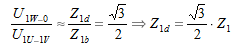
If above proportion between the primary turns of transformers is ensured by their construction, then the secondary voltages of transformers will be identical (Ud=Ub), provided that the numbers of secondary windings are equal (Z2d=Z2b ). In such a case the current modules I1U, I1V and I1W will be equal, and the phase angle between them will be 2π/3.
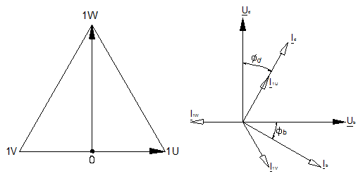
Topographic diagram of voltages and vector diagram of the system
An important advantage of Scott circuit is the fact that with symmetrical 2-phase load also the 3-phase supply network will be loaded symmetrically.
The transformers working in Scott circuits are widely applied in electric heating engineering.
Supplying the track electric circuits is carried out for the reasons of operational safety is usually conducted by means of separation transformers, the parameters and structure of which are adjusted to changeable and difficult working conditions.
Mostly they are used for supplying the devices of automatic line blockades, heating the railway crossovers and supplying the railway traffic control systems.
Transformers supplying the devices of automatic line blockades:
These transformers supply the devices for railway traffic control.
![]()
Description: Linia kablowa – Cable line
![]()
ELHAND transformer, type ET3KOL-16kVA, intended for supplying blockade lines.
The automatic line blockades are used by the Polish Railways (PKP) on the lines with high traffic intensity. They allow to achieve the increase in track flow capacity on the tracks where such devices for railway traffic control are installed. Moreover, due to its structure, they ensure the safety of the railway traffic to a much greater extent than the line devices used in railway engineering in the past. However, the condition for all this is the provision
of failure free supply. For this purpose, the industrial control system circuits are used to form the entire set together with supply transformers.
The supply is executed by the isolating transformers of ET3KOL type. The transformers are installed at both ends of the supply line. This guarantees the reserve for the blockade supply should one of them fail to operate. It is the control systems that steers the respective sequence for combining the transformers. The three-phase isolating transformers in the ET3KOL railway version are adjusted to operation in any climate zone due to their special enclosure and highly effective vacuous impregnation. Due to overvoltage limiters in combination with strengthened insulation, the transformers are resistant to switching overvoltages and lightning surges. Large overvoltage resistance from the supply side during atmospheric discharges reduces the amount of damages to the track electronics used in the track-vehicle impact elements. The application of these transformers allow to reduce the costs of exploitation (the necessity of transmitters repair is eliminated.
Transformers supplying electric heating systems for railway crossovers (EOR):
The transformers supplying the systems for heating railway crossovers (EOR) are untypical isolating transformers, adjusted for operation in the environment with very high humidity and considerable annual and daily temperature amplitudes. They usually operate in the sets of a few transformers, isolating the circuits of electric heaters for heating railway crossovers. These are usually non-service systems, placed in wells or
boxes on the verges of track line. They operate within the range of ambient temperature from -40OC to +10OC. However, they can operate with 20% durable current overload without any harm to transformer insulation. Additionally the transformers are coated with resin, which makes them water-resistant and entirely resistant to the presence of any water that may appear in the box in which they are installed. As opposed to toroidal transformers their inrush currents are small and they have been limited at the design stage. The transformers may be protected against short-circuits with excess current switches S301 with C type characteristics.
![]()
ELHAND transformer intended for supplying the crossovers heating systems, type ET1KOLŻ-2,5kVA.
Transformers supplying the railway traffic control circuits:
These transformers play a responsible role in the devices for railway traffic protection.
Their technical parameters must meet the requirements of EN(IEC)61558 standard as well as sharpened requirements of branch standards regarding no-load current, resistance to short-circuits and overloads and working temperatures.
Our company produces the transformers intended for supplying the railway control systems with power from 40 to 500 VA, type ET1KOL.
![]()
ELHAND transformer intended for supplying the railway traffic control systems, type ET1KOL-0,70 kVA.
It is often necessary to adjust the transformer dimensions to existing machine enclosure. The construction of 5-column core allows to reduce the transformer height.
5-column core contains two unwound external columns which constitute the extension and connection of the lower yoke with the upper one. The application of such magnetic core in 3-phase transformer allows to reduce the section of yokes to about 60% of yoke section in typical 3-column core, maintaining full transformer power and unchanged dimensions of columns.
This way the transformer height is reduced by about 80% of the height of one yoke.

General diagram of 5-column core.
The diagram above presents a core of 3-phase 5-column transformer. Yoke parts of various lenght (m`, m``, n), and various cross-sectional area (Ajm`, Ajm``, Ajn) are distinguished.
In practice several various constructions of 5-column core are applied:
- Equal cross-sections of all yoke sections, amounting to 50-58% of column cross-section (example of designation: 50/50)
- The cross-section of yokes between main columns is about 58%, and the cross-section of return yokes is about 45% of the column cross-section (designation 58/45).
- The cross-sections of all horizontal sections of yokes amount to about 58% of the column section, and the cross-sections of vertical sections of return yokes are about 45% of the column cross-section (designation 58/58-45).
In 5-column transformers produced by our company we often apply the same cross-sections of all yoke sections and they are equal to the half of column cross-sections – 50/50 proportion. In such solution the maximal induction of column yokes is higher by about 5% and smaller by 5-10% in closing yokes in relation to the maximal induction in columns.
50/50 dimensional proportion of core ensures the maximal savings on material and optimal adjusting of transformer size to the existing body of machine.
The yokes closing themselves in 5-column core can constitute a low-reluctance way for the fluxes of third harmonic and its multiple. The flow of third harmonics fluxes would cause a strong deformation of fluxes in wound columns, which would result in non-sinusoidality of phase voltages. In order to prevent that the primary or secondary transformer winding should be linked in the triangle (D), or the primary winding should be linked in the star, with neutral conductor (YN).
![]()
ELHAND 5-column transformer, type ET3oGH.
