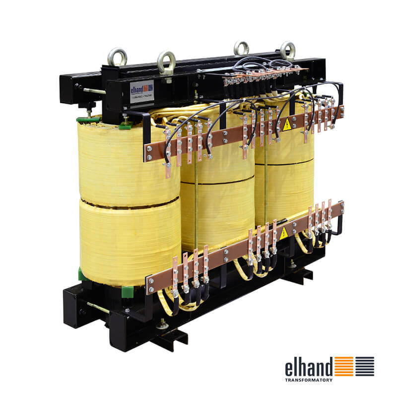
Dreiphasige Leistungstransformatoren ET3S** mit einer Leistung von 10 bis 1600 kVA class „F”
Power transformers are assigned for supplying power electronic devices, and for application in other industrial branches. In standard design, the transformers are adjusted to fastening by means of a base welded into core or screwed angles. If agreed, the transformers may have more tappings. The windings terminals may be placed on one side only, or on both sides of a transformer.
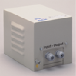
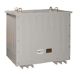
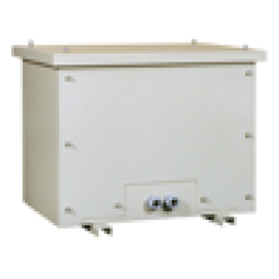
Upon request, the transformers may be assembled in enclosures with the protection degree of IP 23, IP 44 and IP 54 with the possibility to insert supply cables through glands.
Standard enclosures have powder coating - colour RAL 7035.
Detaillierte Informationen:
| Design |
Power transformers are produced in accordance with requirements of: EN/IEC 60076 |
|---|---|
| Insulation class |
F(155oC) - standard |
| Climatic class /environmental class |
C1/E0 - land design; C2/E1 - maritime design |
| Ambient temperature | 40oC |
| Protection degree | IP 00 |
| Protection class | I |
| Frequency | 50/60 Hz |
| Vector group | Dyn5 - standard |
| Primary voltage | up to 1000 V |
| Secondary voltage | up to 1000 V |
| Terminals | screw terminal blocks or cable lugs or copper bus bars |
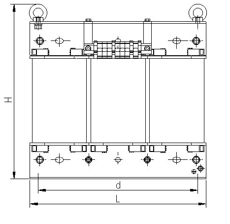
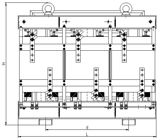
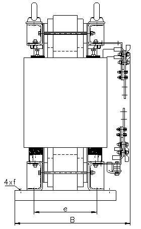
Technische Skizze
 |
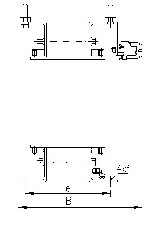 |
| Design with power up to 160kVA | |
 |
 |
| Design with power above 160kVA | |
Dimensionstabelle
Technical data of power transformers typ ET3S, insulation class F, voltage ratio 400V//400V**
| Type | Power [kVA] |
L [mm] |
B [mm] |
H [mm] |
d [mm] |
e [mm] |
f [mm] |
Weight [kg] |
|---|---|---|---|---|---|---|---|---|
| ET3S_* - 10 | 10 | 360 | 200 | 331 | 310 | 162 | 11 x 15 | 71 |
| ET3S_* - 12,5 | 12,5 | 420 | 200 | 375 | 370 | 158 | 11 x 15 | 82 |
| ET3S_* - 15 | 15 | 420 | 210 | 375 | 370 | 168 | 11 x 15 | 91 |
| ET3S_* - 16 | 16 | 420 | 210 | 375 | 370 | 168 | 11 x 15 | 92 |
| ET3S_* - 20 | 20 | 480 | 294 | 425 | 430 | 190 | 13 x 18 | 117 |
| ET3S_* - 22,5 | 22,5 | 480 | 300 | 425 | 430 | 200 | 13 x 18 | 129 |
| ET3S_* - 25 | 25 | 480 | 305 | 425 | 430 | 210 | 13 x 18 | 139 |
| ET3S_* - 30 | 30 | 480 | 325 | 425 | 430 | 220 | 13 x 18 | 154 |
| ET3S_* - 40 | 40 | 540 | 350 | 485 | 490 | 240 | 13 x 18 | 195 |
| ET3S_* - 50 | 50 | 540 | 370 | 485 | 490 | 260 | 13 x 18 | 230 |
| ET3S_* - 63 | 63 | 540 | 390 | 485 | 490 | 280 | 13 x 18 | 265 |
| ET3S_* - 75 | 75 | 690 | 480 | 555 | 590 | 220 | 13 x 18 | 300 |
| ET3S_* - 80 | 80 | 690 | 480 | 555 | 590 | 220 | 13 x 18 | 305 |
| ET3S_* - 100 | 100 | 690 | 410 | 555 | 590 | 250 | 13 x 18 | 365 |
| ET3S_* - 115 | 115 | 690 | 440 | 555 | 590 | 270 | 13 x 18 | 415 |
| ET3S_* - 120 | 120 | 720 | 450 | 650 | 620 | 260 | 17 x 25 | 425 |
| ET3S_* - 125 | 125 | 720 | 450 | 650 | 620 | 260 | 17 x 25 | 430 |
| ET3S_* - 160 | 160 | 720 | 450 | 650 | 620 | 300 | 17 x 25 | 550 |
| ET3S_* - 200 | 200 | 980 | 460 | 870 | 760 | 375 | Ø17 | 690 |
| ET3S_* - 225 | 225 | 1045 | 480 | 905 | 760 | 385 | Ø17 | 800 |
| ET3S_* - 250 | 250 | 1045 | 480 | 940 | 760 | 385 | Ø17 | 830 |
| ET3S_* - 315 | 315 | 1140 | 500 | 1010 | 760 | 394 | Ø17 | 1025 |
| ET3S_* - 400 | 400 | 1200 | 525 | 1065 | 760 | 394 | Ø17 | 1225 |
| ET3S_* - 500 | 500 | 1245 | 550 | 1100 | 760 | 416 | Ø17 | 1430 |
| ET3S_* - 630 | 630 | 1290 | 560 | 1150 | 760 | 416 | Ø17 | 1810 |
| ET3S_* - 800 | 800 | 1410 | 600 | 1285 | 760 | 433 | Ø17 | 2175 |
| ET3S_* - 1000 | 1000 | 1455 | 610 | 1565 | 760 | 433 | Ø17 | 2695 |
| ET3S_* - 1250 | 1250 | 1620 | 650 | 1500 | 760 | 473 | Ø17 | 3350 |
| ET3S_* - 1600 | 1600 | 1670 | 700 | 1580 | 760 | 473 | Ø17 | 3830 |
*) - for transformer design with climatic/environmental class C2/E1 (maritime design W/3 or tropical design T/3) the letter "M" or "G" ought to be added depending on final application
**) - this table was prepared basing on the technical specification for transformer with voltage ratio 400//400 at 50 Hz and operating under normal conditions. For other conditions and data the values may change
Note:
Manufacturer reserves the right to make changes resulting from the continuous development of products offered.
If requested in advance, it is possible to manufacture transformer in other version.
for horizontal mounting IP23
for vertical mounting IP23
vertical design IP44
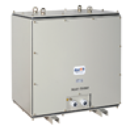
vertical design IP54
Andrzej Pietkiewicz


